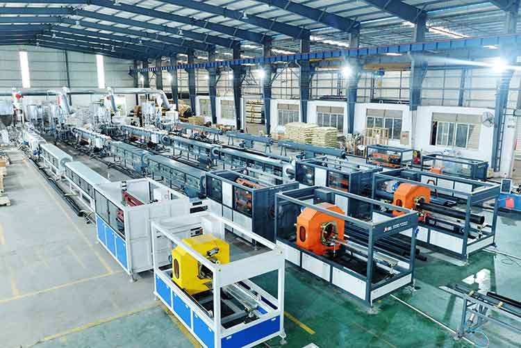
Однією з основних машин, яка революціонізувала галузь виробництва пластикових труб, є екструдер.
Це універсальний, багатофункціональний і легкий екструдер, який може виконувати широкий спектр завдань. Будь то плавлення пластику, змішування і гомогенізація, формування, дегазація і деволатилізація або модифікація, екструдер можна використовувати для всього цього.
У цьому посібнику ми розглянемо всі ключові аспекти цієї машини – від її визначення, типів, функцій кожної секції, роботи, компонентів до принципу її функціонування.
Що таке екструдер?
Екструдер — це промислове обладнання, яке використовується для плавлення та екструзії таких матеріалів, як пластик і гума. В основному воно поділяється на два типи: одношнекове та двошнекове. Принцип його роботи полягає в пластифікації твердих матеріалів до однорідної розплавленої маси та безперервній екструзії їх у форму за допомогою сили зсуву, тиску та зовнішнього нагрівання, що створюються обертанням шнека.
Типи екструдерів та їх використання
Одношнековий екструдер
Вона складається з системи передачі (двигун + редуктор), системи екструзії (циліндр + шнек) та системи контролю температури і підходить для безперервного виробництва труб, профілів тощо. Наприклад, модель ZJL-200B оснащена сенсорним екраном та повітряним охолодженням змішувача, що забезпечує контроль точності на рівні лабораторії.
Двошнековий екструдер
Двошнековий екструдер працює в тандемі, що робить його придатним для високоточного змішування та складної обробки матеріалів. Наприклад, він може регулювати вологість, температуру та структуру волокон при розробці рослинних білків.
Загальні компоненти екструдера
Зона годування
Зона подачі є зоною зберігання сировини екструдера. Сировина завантажується в зону подачі у вигляді гранул або порошку, а потім транспортується вниз по потоку за допомогою обертового шнека.
Гвинт
Шнек є основним компонентом екструдера. Він складається з низки різьблень і зазвичай розташований всередині циліндра. Основна функція шнека полягає в нагріванні, плавленні, змішуванні та просуванні сировини вперед. Конструкція шнека та форма різьблення можуть регулюватися відповідно до різних матеріалів та вимог до продукту.
Бочка
Бочка — це циліндричний контейнер, в якому розміщений шнек. Зазвичай вона виготовляється зі спеціальних сплавів або покриттів, щоб витримувати високі температури та тиск. Її основна функція — нагрівати та плавити сировину, підтримуючи постійний тиск.
Системи опалення та охолодження
Екструдери зазвичай оснащені нагрівальними елементами, такими як електричні нагрівачі або нагрівальні стрічки, для нагрівання сировини до температури плавлення та регулювання температури. Також необхідні системи охолодження, щоб екструдований продукт швидко охолоджувався і зберігав бажану форму.
Матриця або екструзійний головка
Матриця або екструзійна головка визначає форму та розміри кінцевого продукту. Сировина проходить через екструзійну головку і далі переробляється в бажаний продукт, такий як труби, плівки та профілі.
Система управління екструдером
Система управління контролює та регулює різні параметри екструдера, такі як температура, тиск та швидкість шнека. Регулювання цих параметрів має вирішальне значення для забезпечення якості продукції.
Системи різання та намотування
Деякі продукти, такі як труби або плівки, після екструзії необхідно розрізати на певні відрізки або намотати в рулони. Ці системи виконують ці етапи обробки.
Система приводу
Приводні системи забезпечують потужність, необхідну для обертання гвинта та переміщення інших механічних компонентів. Зазвичай ці системи складаються з електродвигуна, редуктора швидкості та трансмісії.
Функція кожної секції екструдера
Одношнековий екструдер є триступеневим екструдером, який складається з секцій подачі, зменшення та екструзії.
Розділ «Годування»
Сировина для екструзії зазвичай має гранульовану форму. Подавальний пристрій, також відомий як бункер, забезпечує безперервний потік матеріалу в циліндр екструдера. Він нагадує лійку Бюхнера і має конічну або квадратно-конічну форму. Нижня частина бункера, де він з'єднується з циліндром, є отвором для подачі, оснащеним запірним пристроєм для регулювання та перекриття потоку матеріалу. Охолоджувальні затискачі оточують отвір для подачі, щоб запобігти передачі тепла від високої температури потоку матеріалу до бункера, запобігаючи нагріванню та липкості пластику всередині бункера, що може призвести до нерівномірної подачі та перешкоджання потоку матеріалу. Збоку бункера розташований скляний оглядовий отвір та калібрувальні та вимірювальні пристрої. Деякі бункери також мають теплосушильний вакуумний клапан для запобігання поглинанню пластиком вологи з повітря, перемішувальний пристрій для запобігання утворенню “залізничних мостів”, спричинених порошковим пластиком, та пристрій, що автоматично подає матеріал через рівні проміжки часу.
Сегмент скорочення
Цилиндр, також відомий як екструдер, є металевим циліндром, що піддається нагріванню та навантаженню. Розплавлення та усадка матеріалу відбуваються повністю всередині циліндра. Робоча температура під час екструзії зазвичай становить від 180 °C до 290 °C, а внутрішній тиск досягає 60 МПа. Нагрівальні та охолоджувальні пристрої встановлюються зовні циліндра, зазвичай у три або чотири етапи. Зазвичай використовуються резисторні або індукційні нагрівачі, хоча також можливе використання радіаційного нагрівання. Мета охолодження — запобігти перегріванню пластику або швидко охолодити пластик під час вимкнення, щоб запобігти плавленню. Охолодження зазвичай здійснюється за допомогою повітря або води. Цилиндр повинен витримувати високий тиск і мати достатню міцність на стиск і жорсткість, а також гладку внутрішню поверхню. Цилиндр зазвичай використовується для запобігання зносу і корозії. Тертя від перегріву пластику запобігає тертя, а також підтримує поверхню шнека екструдера трохи прохолоднішою, ніж циліндр, щоб запобігти прилипанню матеріалу до нього і полегшити транспортування матеріалу.
Секція екструзії
Шнек екструдера підвішений у центрі циліндра за допомогою упорного підшипника, вирівняного з віссю циліндра без значного відхилення. Мінімальний зазор між шнеком екструдера і циліндром дозволяє пластику піддаватися сильній зсувній силі, плавлячи і просуваючи його вперед.
Зрозумійте, як працює екструзія
Принцип роботи екструдера полягає в пластифікації твердого матеріалу до однорідної розплавленої маси та безперервному видавлюванні її у форму за допомогою сили зсуву, тиску та зовнішнього нагрівання, що створюються обертанням шнека.
Етап транспортування матеріалу
Тверда сировина надходить у барабан із бункера і просувається вперед та ущільнюється під дією тертя обертового шнека, залишаючись твердою.
Транспортувальна секція одношнекового екструдера має глибоку спіральну канавку, що забезпечує ефективне транспортування.
Етап пластифікації та стиснення
Об'єм гвинтового каналу поступово зменшується, а матеріал плавиться під дією зсувних сил і зовнішнього нагрівання. Приблизно 80% тепла надходить від механічного зсуву, а 20% — від зовнішнього нагрівання.
Двошнекові екструдери забезпечують більш рівномірне зсунення та змішування завдяки “O-подібному” руху взаємозачеплених шнеків.
Етапи вимірювання та екструзії
Розплав точно контролюється на етапі дозування за витратою та тиском, а потім формується у бажану форму (наприклад, трубку або плівку) через матрицю.
Стабільність температури має вирішальне значення для забезпечення якості продукції.
Як обслуговувати екструдер
По-перше, екструдерне обладнання слід розміщувати у провітрюваному місці, щоб забезпечити відведення тепла від двигуна та ефективно продовжити термін його експлуатації; машина повинна бути добре заземлена.
Регулярно виконуйте технічне обслуговування та перевіряйте гвинти інструменту. Після 1 години використання нової машини затягніть гвинти рухомих і нерухомих ножів за допомогою інструментів, щоб посилити кріплення між лезом і тримачем інструменту. Регулярно додавайте мастило до підшипників, щоб забезпечити змащення між підшипниками. Щоб забезпечити гостроту різання інструменту, його слід часто перевіряти, щоб переконатися в його гостроті та зменшити непотрібне пошкодження інших компонентів, спричинене тупими лезами. Регулярно проводьте технічне обслуговування та перевіряйте, чи не ослаблений ремінь, і вчасно затягуйте його.
Перезапуск – Перед другим запуском очистіть машину від залишків подрібненого матеріалу, щоб зменшити опір при запуску. Регулярно відкривайте кришку інерційного механізму та кришку шківа і очищайте вихід для золи під фланцем, оскільки порошок, що виходить з дробарки, потрапляє в підшипник валу.
Заміна деталей – При заміні ріжучого інструменту зазор між рухомим і нерухомим ножами повинен становити 0,8 мм для дробарок потужністю понад 20 к.с. і 0,5 мм для дробарок потужністю менше 20 к.с. Чим тонший перероблений матеріал, тим більший зазор можна відповідно відрегулювати.